PWM with STM32 using HAL or LL

This guide will show you how to set up a SMT32 microcontroller to generate a PWM signal using a timer. It will show you how to do it with two approaches. First using HAL and then with the LL drivers from ST Micro. There are many similar guides on the internet, but I want this guide to be a bit more in depth on the process and try and point out the many, many annoying pitfalls you could find yourself in. I will also focus more on the LL method instead of the HAL.
Table of Contents
HAL or LL
There are two (well, three) approaches to what kind of libraries to use. HAL or LL, or the third which is write your own. There is no "right choice" what I can see. The choice should be guided by requirements or interest level.
HAL
HAL is short for Hardware Abstraction Layer. It is supplied by ST Micro with the intention to
- Offload some work into the abstraction layer
- Make code more portable between MCUs in the SMT32 series
- Standardize the API
The API is quite helpful to make development faster as some things are given "for free". The problem with using it is that it can do things behind the scenes to make writing code more straightforward. Because of this, it is possible to have problems because the HAL does things to assist you, that you might not have intended and that are not (in my opinion) fully documented. I had a project where I lost a few days of troubleshooting because I wanted to do something clever with peripherals interrupt flags, and did not know that the HAL functions cleared them automatically before I could read them. It is apparently also adding some performance penalty, but I am not sure if that matters for hobbyist use. I am also unsure how true that statement even is.
Low Level
The low level libraries provide a more hardware close and bare bones experience. They provide functions for accessing registers controlling the peripherals, but you will need to use the reference manual much more when developing the application. There is also no timeouts, error management or protection against simultaneous access.
Complicated peripherals have no LL drivers, complicated peripherals mean peripherals with a complex software stack, such as USB.
Get a project going
First, lets start a project for the timer demonstration. Start CubeMX(IDE), choose your MCU and create the project in some folder. This demonstration will use the STM32C031K4T6 MCU as it is the one I use in another project, but this should be largely translatable to most MCUs from ST micro. If you have a development board from ST, choose that one instead of a MCU and you can skip the clock setup step
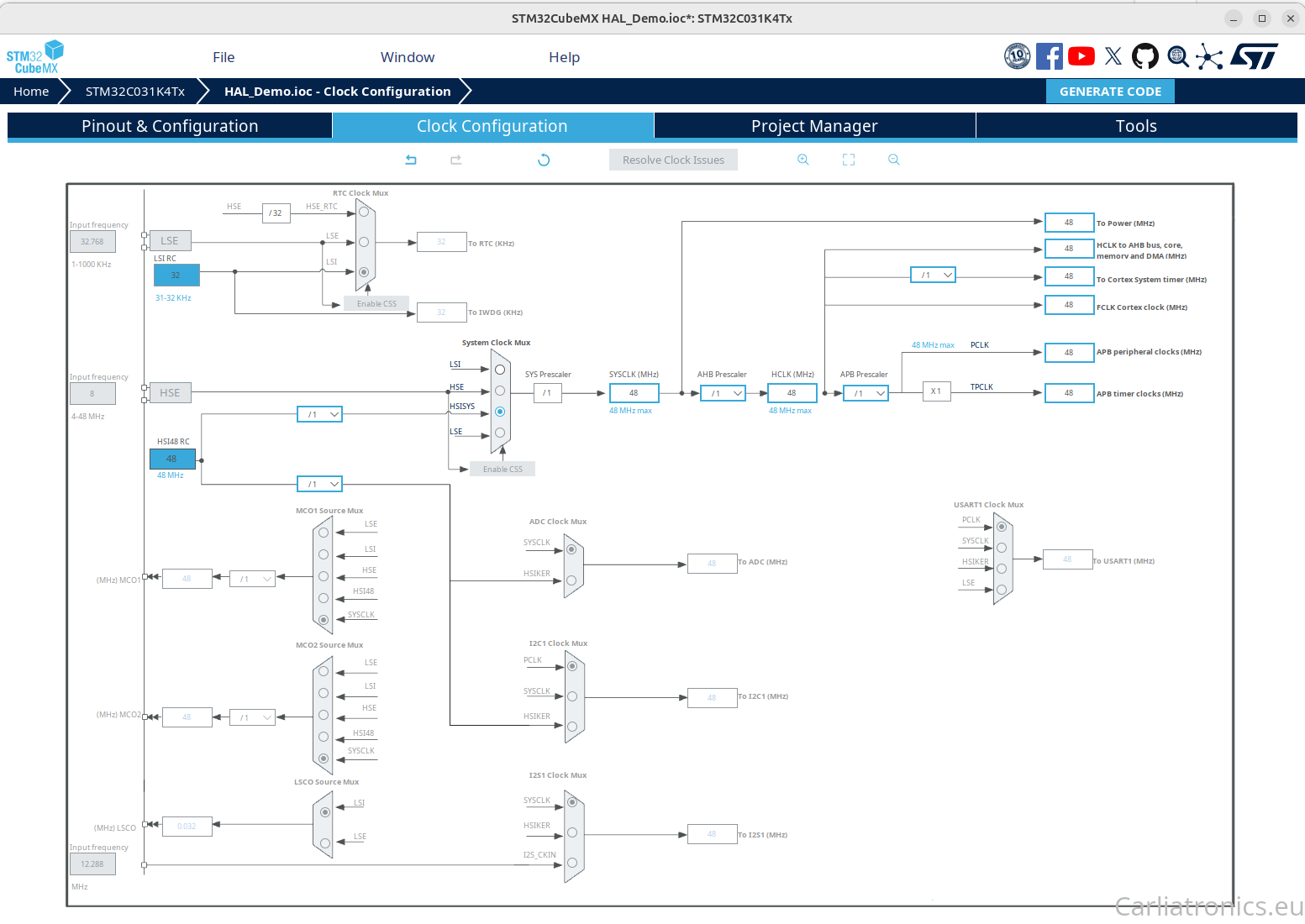
Next, lets set up the clocks. Open the clock configuration tab. You will now see the setup for the different clocks you can use. Exactly what you should use here depends on your hardware. My example will use the HSI48 RC as a clock source in the System Clock Multiplexer because my board does not have an external oscillator. If you have an external oscillator, use that one instead. Now, set the different prescalers so that your clocks are running at the speed they should. This will vary per MCU. Mine can run at up to 48MHz for all clocks. The interesting clock for the timer setup is the APB Timer clock.
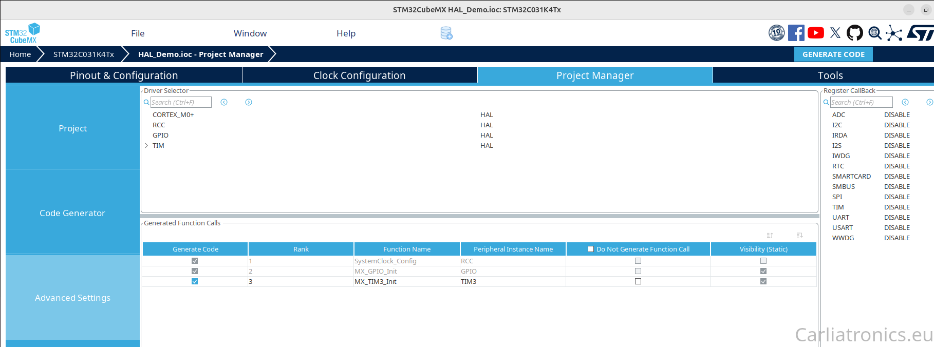
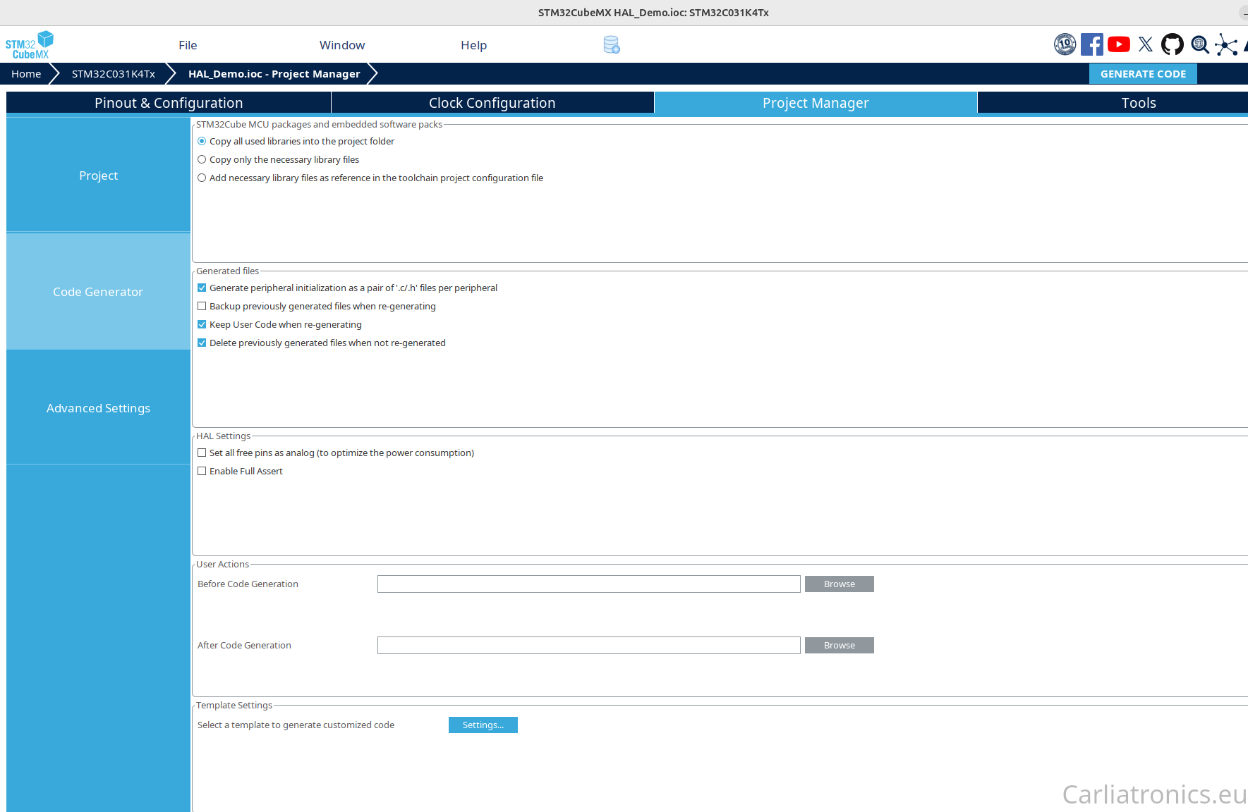
Now, go to the project manager tab. Create a good name for your project and specify where to save it. Open the code generator sidebar. I prefer to ask to only copy necessary library files and to generate a pair of c and h files for each peripheral. This is critical for larger projects, or else you end up with an absolutely gigantic "main.c" that is impossible to get an overview of. The rest can be left as-is. At last, go to advanced settings. Here you should see a summary of peripherals that are enabled at this point. It should only be "RCC" which is the system clocks. It is also here you can choose between generating HAL or LL setup code.
Now it is time to set up the timer. Open the pinout and configuration tab. Choose a suitable pin that has a timer connected to it. Here, I choose PB3 which is mapped to timer 3. You could choose any timer, but try to use a simple one. Later in the guide it will become clear why this is the case.
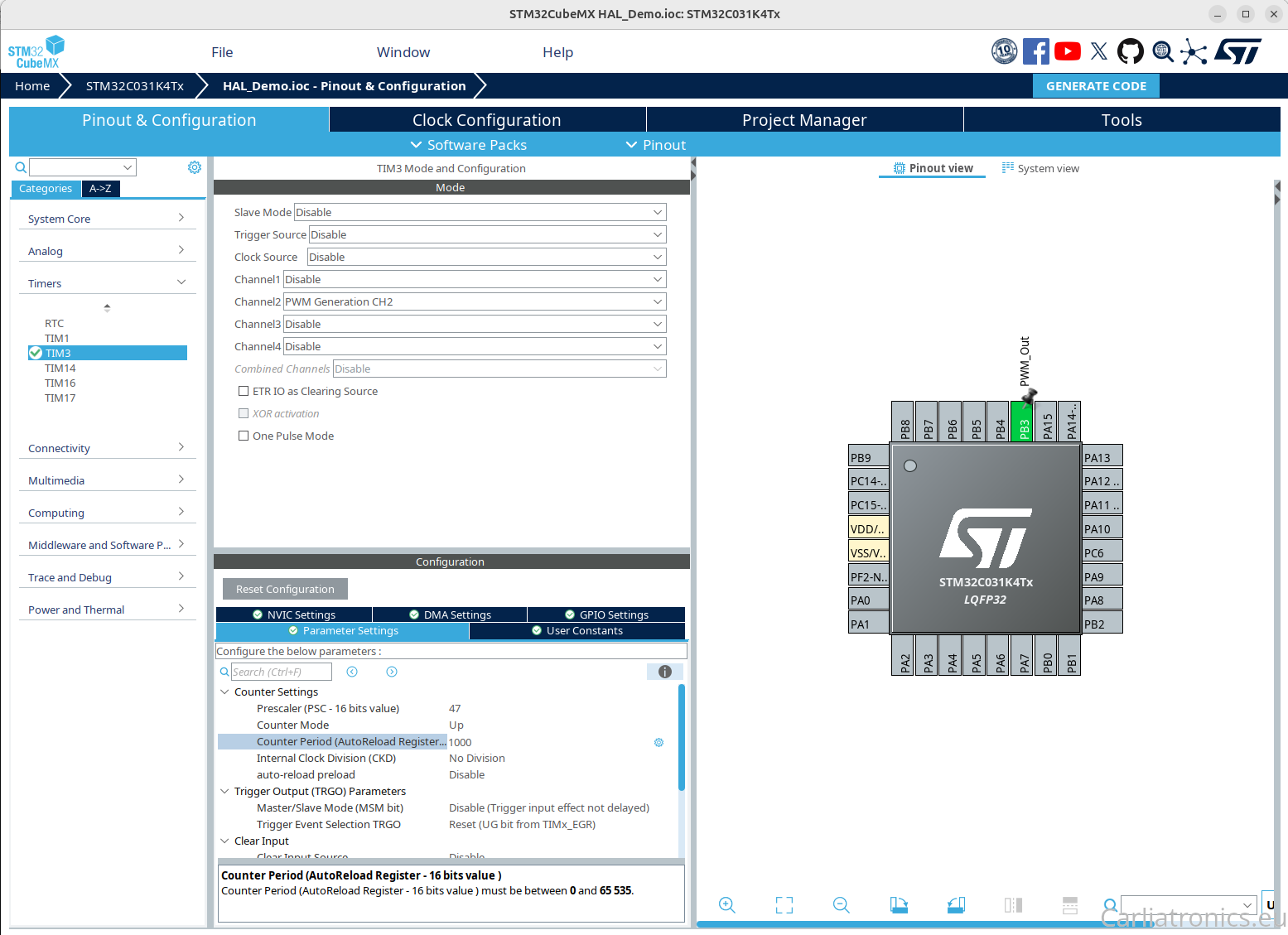
Expand the timer selection in the left pane. The timer you chose should now be green. Click on it to select it for configuration. A new pane will open. The "mode" section will look slightly different depending on the timer. But in general, you need to select two things if they are available
- The clock source
- What the channel you want to use should do
Set the clock source to what you want, internal in my case. Then enable the channel that is mapped to your selected pin to PWM Generation CH2 where 2 is the channel selected. Once you have done this you can go into the configuration section. Here there are more things to set up. Lets go through what they mean one-by-one
Counter settings
Prescaler
The prescaler is a register where you select how many clock pulses are required for each increment of the counter value. The setting in cubeMX is (n+1), meaning a value of 3 will require 4 clock pulses for each increment of the counter. Set this to something useful. I will use 65 000 for this example
Counter mode
This selects how the counter should count, up or down. Pretty self explanatory. Set it to "up".
Counter period
This setting is sometimes also called the Autoreload register and it selects what number the counter will "roll over" at. This will effectivly set the max resolution your PWM can have, and combined with the prescaler it will also set what the PWM frequency is. This demonstration should be possible without an oscilliscope so I am targeting a frequency of 1 Hz. The frequency can be calculated as
Clock / (Prescaler x Counter period)
I am assuming a 16-bit timer and 16-bit prescaler, so a counter period of 700 and prescaler of 65 000 will give a frequency of around 1Hz.
Internal clock division
This controls the ratio between internal clock and the sampling of the input when used in input capture mode. I have not used it so can not say much about it.
Auto reload preload
This setting is a bit unintuitive, and for simple things like LED PWM it does not matter much. What it does is control how a changed Auto reload value is starting to get used. Setting it to disabled will update it immediately, while having the setting to enabled will let the counter reach the old value first and then update the counter period when the new cycle begins.
Channel configuration
This part is further down in the menu and will have different names depending on what the channel has been configured to do. Here it will be called PWM Generation Channel 2. Expand the settings for further tuning
Mode
This is the selection for different modes on PWM. What options are availible here depends on your selected timer. PWM mode 1 is a "simple" PWM. There are many more advanced modes to select that I will not go into here.
Pulse
The pulse is how the duty cycle is controlled. The counter will always count from 0 -> Counter period over and over. When the value in "pulse" is exceeded the output will switch state. Make sure this value is smaller than the counter period. I choose 350 for a close to 50% Duty cycle on startup.
Output compare preload
This works just as the preload setting for auto reload. Enabling it will let the current PWM cycle complete before the pulse setting is applied to the output.
CH Polarity
This setting control what the polarity should be for when the pulse is active. High mean it is pushed to logic high.
CH Idle state
This setting control what the output of the timer is when it is inactive. Meaning before started or when stopped. Set this to reset, meaning that the output is off when the timer is disabled.
Generate and use code
Now that all settings are done it is time to generate the code. Press "generate code" and wait for the code generation to finish. Start your IDE (or switch to CubeMXIDE code tab) to use the code you generated.
Taking a look at the generated code
We can start by taking a look at the code that was generated to understand a bit what it does. The code generated for timer control should be in a file called "tim.c". The important part that was generated is found in MX_TIMx_Init, which is the function that sets up the timer using the HAL drivers. You can see that all choices you made are put into a struct that then is used as an argument in the the HAL functions that configure the base timer settings, the PWM settings and at last the timer channel settings. If you are interested you can explore what these functions do by following them into the HAL driver libraries, where you can see how they in the end are manipulating registers related to the different properties.
PWM with HAL
Now, lets do the last step. Open the "main.c" file. Scroll down until you find the comment
/* USER CODE BEGIN 2 */
Now you only need to do one thing to start the PWM generation. Call the HAL function to enable a timer channel. The function take a pointer to the timer and reference to the channel as arguments. Using the autocomplete feature and the defined names you do not need to worry much about the type difference between these two constants, just set them in the correct place
HAL_TIM_PWM_Start(&htim3,TIM_CHANNEL_2);
To make it a bit more interesting we will change the period on a pattern. Add a "last time" variable to store the systtick for last PWM duty cycle change under the PWM start line. Add a "pulse" variable to store a modified pulselenght as well
uint32_t last_time = HAL_GetTick();uint16_t pulse = 0;
Then add this into the "while(1) loop" to change the duty cycle once every 5 seconds
if ( (HAL_GetTick() - last_time ) > 5000 )
{if(pulse>=700){ pulse=0;} else {
pulse = pulse + 100;
}
HAL_TIM_SET_COMPARE(&tim3,TIM_CHANNEL_2,pulse);
last_time = HAL_GetTick();
}Upload and test
PWM with LL
This part of the guide will show how to do the same using the low level drivers. The settings can be used as is, but you need to open the project management tab->Advanced settings to generate LL instead of HAL code. It is theoretically possible to mix HAL and LL, but I find it needlessly confusing to do. Click the "HAL" text on the TIM row and change it to LL. Do the same with RCC. Press generate code again.
If you explore the tim.c file you will now see that the generated code looks familiar but different. The same settings can be seen get set in some struct, and then used as an argument when calling a init function.
Now lets open the main.c file again. There are some changes to be made here. The HAL functions need to go and be replaced with their Low level equivalents. The line
HAL_TIM_PWM_Start(&htim3, TIM_CHANNEL_2);
is replaced withLL_TIM_EnableCounter(TIM3);
LL_TIM_CC_EnableChannel(TIM3, LL_TIM_CHANNEL_2);HAL_TIM_SET_COMPARE(&htim3, TIM_CHANNEL_2, pulse);LL_TIM_OC_SetCompareCH1(TIM3, LL_TIM_CHANNEL_2);LL_SYSTICK_EnableIT();uint32_t systick_counter=0;systick_counter++;uint32_t get_systick_counter(){return systick_counter;}Open the header file for the interrupts, xxxx_it.h. Add the definition of the helper function hereuint32_t get_systick_counter();
Replace the calls to HAL_GetTick() with your new helper function. Save, compile and upload the program to your controller. You should have exactly the same behaviour now as when HAL was used. If it does not work, make sure you actually started all counters etc.
Some problems
Now, this sounded pretty simple, right? Well sometimes it is and sometimes very much not. I have found some problems you can have poorly explained in the internet and quite hidden in the reference manual. This caused me two evenings of frustration not getting PWM generation to work for my project. For now I have no other solution than "keep trying". It is often a simple register not set correctly, which is really easy to fix but frustrating to find as a beginner. Compared to the arduino world it is basically a requirement to have a functional debugger to have a chance to fix problems.
The backside of advanced timers
In the beginning I said that there are pitfalls. The problem I ran into recently was one of them. I have a project I will talk more about later. This project require PWM generation on 4 channels on timer 1 with the MCU I have chosen. The MCU is the same mentioned in the beginning of this post, the STM32C031K4T6. Timer 1 on this MCU is very competent, and is called out as an Advanced-control timer in the reference manual. This did not seem as a problem at first glance. It support the simple features, so I simply ignore the advanced ones and everything is OK, right? Wrong! I spend two nights getting it to work. One reason it took so long is that I have not gotten debugging to work on my new computer so I was coding blind. What happened is quite typical for how beginners can get very stuck, so my experience can maybe help someone
The reference manual for timer 1 is long. Very long. All in all, just about 100 pages. There is the typical info for how to program it following the "typical" setup as one would expect. Enable the timer, enable auto reload, enable the channel and write a value to the output compare register. Straightforward stuff. Then there is this line, on one of the pages explaining that the output is controlled by more than just the result of the output compare
OCx polarity is software programmable using the CCxP bit in the TIMx_CCER register. It
can be programmed as active high or active low. OCx output is enabled by a combination of
the CCxE, CCxNE, MOE, OSSI and OSSR bits (TIMx_CCER and TIMx_BDTR registers).
Refer to the TIMx_CCER register description for more details.
Which I did not think much about at the time. I might even have skimmed over it as I had found the info I needed to see that I set the correct registers. The quoted sentence does not actually say what to do, just that something need to be set correctly. Further reading show a link to table 66, which nicely tells you how to correctly set MOE, OSSR and OSSI to get the output to do what I wanted. These bits can be set in CubeMX, but the settings has other names. The settings where Automatic Output State (MOE) and Off State Selection For Run Mode (OSSR), both of which must be enabled!
I have run into similar issues with other peripherals, and might write guides for those struggles as well. But for now I will leave it at
- Use simple peripherals if you can. KISS is very much a good strategy.
- Read the reference manual carefully and don't assume you know how it works before you read it.
- You need your debugger up and running.