H-Bridge Module
Some time ago I did a H-bridge module as a testing device for the Skylight Project, but I i never wrote about it. So here follows a short description of the module as well as a H-bridge in general.
What is an H-bridge
An H-bridge is an electrical circuit with 4 transistors that is used to drive a DC motor with both speed and direction control. The circuit is called an H-bridge because it kind of looks like an H, with two transistors in each vertical part and the motor in the middle horizontal part.

In order to drive the motor in one direction, Q1 and Q4 are closed. If the other direction is needed Q2 and Q3 are closed instead. For speed control it is possible to apply a PWM signal to the high side MOSFET. When that is done, current will circulate through the still open low side MOSFET and up back through the body diode of the second low side MOSFET.
My module
My module uses two half-bridge drivers to switch the 4 MOSFETs. The driver IC is a DGD05473 from Diodes Incorporated, a pretty cheap but reasonably competent half-bridge driver. On top of the FETs there are LEDs to visualise the signals being sent to the bridges for easier debugging. The module should be able to deliver about 8A of current up to around 14V or so with the MOSFETs currently in use. The schematic for one of the half bridges in the module looks like this

The module has right now only been tested with a resistive load, but it had no problem delivering the 8A I was hoping for. The module can deliver the quite high current because of reasonably low power loss in the FETs combined with the cooling performance of the PCB. The PCB is a 4 layer PCB with loads of vias under the FETs for good transport of both heat and current. The PCB design looks like this:
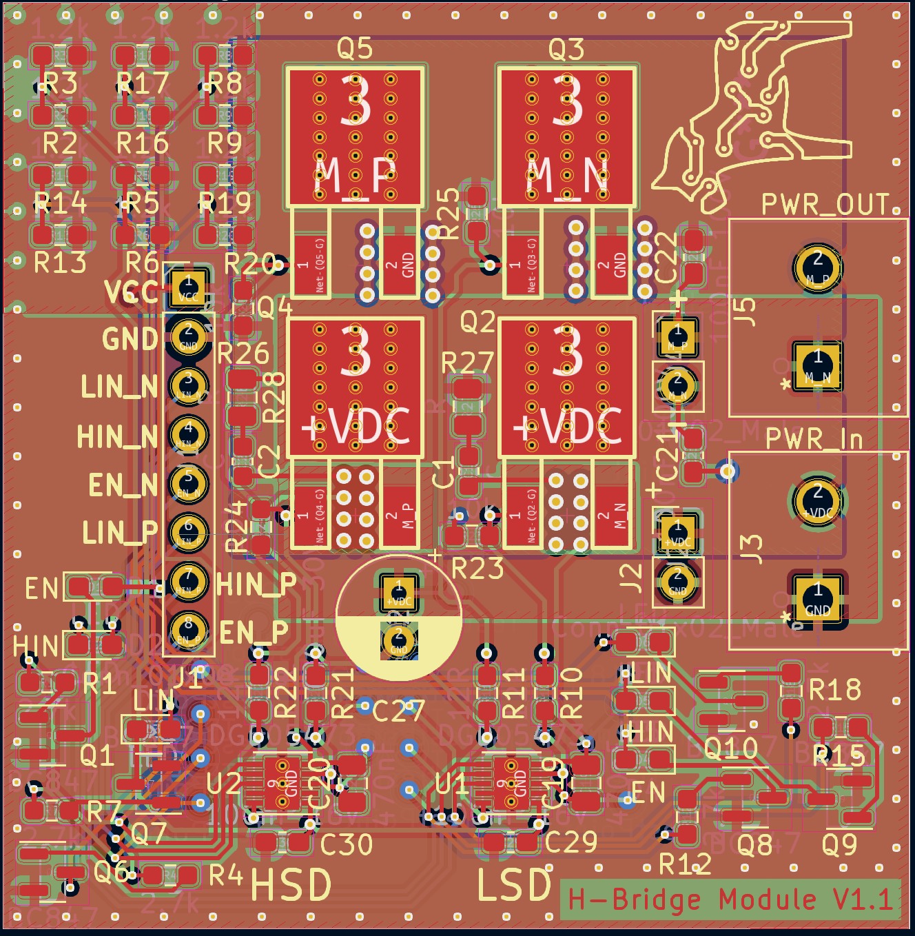
The top layer is a component, signal and +12V layer, layer two has some signals and negative motor power, layer two some signals and positive motor power and the last layer is ground plane. It is not the best board stackup ever made as I learned since I did the design.
Future improvements
Some things are not that good with this module. The biggest is probably the lack of external recirculation diodes. The transistor do have the intrinsic body diodes, but they are a bit power limited compared to a dedicated part. One other thing would be addition of current feedback for even better control of the motors. I would also like to exchange the FETs to another part number. They are good enough but the margins for overvoltage are a bit on the thin side.
But before all of this is done it will be tested with a proper motor load to see what happens. Maybe there are some other problems that I need to figure out, or have missed completely. It would be stupid to just do changes and then have V2 blow up immediately!